

Introduction
Have you ever wondered how an electric car moves when you apply the accelerator? The answer often resides in a vital electronic mechanism known as the Motor Control Unit—or MCU for short.
This tutorial will explain in simple, understandable terms what an MCU does, how it operates, why it matters, and how it fits into the larger EV picture.
What Is a Motor Control Unit (MCU)?

The electrical component in an electric car that connects the battery to the drive motor is called a Motor Control Unit (MCU). Its function is to regulate the amount, timing, and type of energy flow so that the electric motor operates smoothly and effectively. It regulates speed, torque, acceleration, and energy recovery while braking.
Why the MCU Matters in an EV?
Consider the MCU as the intermediary between the EV’s motor and battery:
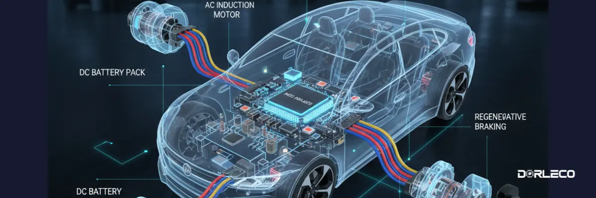
- It takes electricity stored as direct current (DC) in the battery
- Transforms it into alternating current (AC), which the motor may utilize.
And modifies that power to suit your needs, such as accelerating or decelerating. The MCU has a significant influence on the following since it carefully regulates torque and speed:
- Vehicle responsiveness
- Efficiency of energy
- Smooth driving
- Optimization of range
How an MCU Works (Simply Explained)
 When you apply the accelerator, the following internal processes take place:
-
Driver Input Signals
Through signals from sensors and the vehicle’s central controller (often the Vehicle Control Unit, or VCU), the MCU interprets commands for braking and throttle. -
Conversion of Power
It transforms the battery’s DC electricity into AC power that the motor can use. -
Control of Speed and Torque
In order to modify motor speed and torque in real time, the MCU precisely modifies voltage and current. -
Braking with Regeneration
The MCU can increase efficiency and range by reversing the motor’s function when you brake, returning some energy to the battery. -
Security and Safety
In order to prevent overvoltage, overcurrent, and overheating of the motor and battery, modern MCUs keep an eye on electrical conditions.
Essential Elements of an MCU
Although each manufacturer’s internal architecture may differ, the majority of MCUs consist of:
- Processor/Microcontroller manages algorithms for control
- Power Stage/Inverter Converts DC to AC
- Feedback Interfaces & Sensors Regarding motor speed and rotor position
- Safety and Protection Circuits To avoid errors and harm
Together, these elements ensure that your EV reacts as it should.
MCU vs VCU: What’s the Difference?
It’s easy to mix them up. Here’s a simple way to remember:
| Component | Role |
|---|---|
| VCU (Vehicle Control Unit) | The “brain” of the entire EV—coordinates subsystems like motor, battery, thermal, braking, and more. |
| MCU (Motor Control Unit) | A specialized controller that handles motor power and motion based on commands from the VCU. |
So the VCU tells what needs to happen, and the MCU figures out how to make the motor do it.

Real-World Benefits of a Good MCU
EV driving is made possible by a superior MCU:
- More seamless
- More effective
- Greater awareness of energy
- Better at regenerative braking
- More dependable and secure
More useful range per charge and improved driving feel are the results of good motor control.
For instance, MCUs’ Role in Daily Driving
- When You Begin
MCU increases the motor’s spinning speed without causing any jerks.
- When You Gain Speed
It effectively and progressively increases torque.
- When Applying the Brake
It returns energy to the battery while slowing down the car. The smooth running of electric vehicles is a result of this combination of actions.
Final Thoughts
Although it may not be the most visually appealing component of an EV, the motor control unit is crucial. From launch to cruising to regeneration, it is the part that enables the motor to react intelligently and smoothly to your inputs.
An electric car would feel unpredictable, inefficient, and noisy on the road without a well-designed motor control unit. Therefore, knowing the Motor Control Unit is important whether you’re an engineer, an EV fan, or a decision-maker in the automotive industry.