

Introduction
Whether you’re designing a city e-rickshaw or a 40-ton electric truck, getting the I/O count wrong on your vehicle control unit is one of the most expensive mistakes you can make early in a program. Here’s how to get it right. To select the right VCU I/O count for EV, list every sensor, switch, actuator, and communication interface the vehicle needs, add 20–30% headroom for future changes, and then match that total to a VCU platform that supports the right mix of analog inputs, digital I/O, PWM channels, and serial buses. Undersizing forces costly workarounds; oversizing wastes money. This guide walks you through both.What exactly is VCU I/O count for EV—and why does count matter?
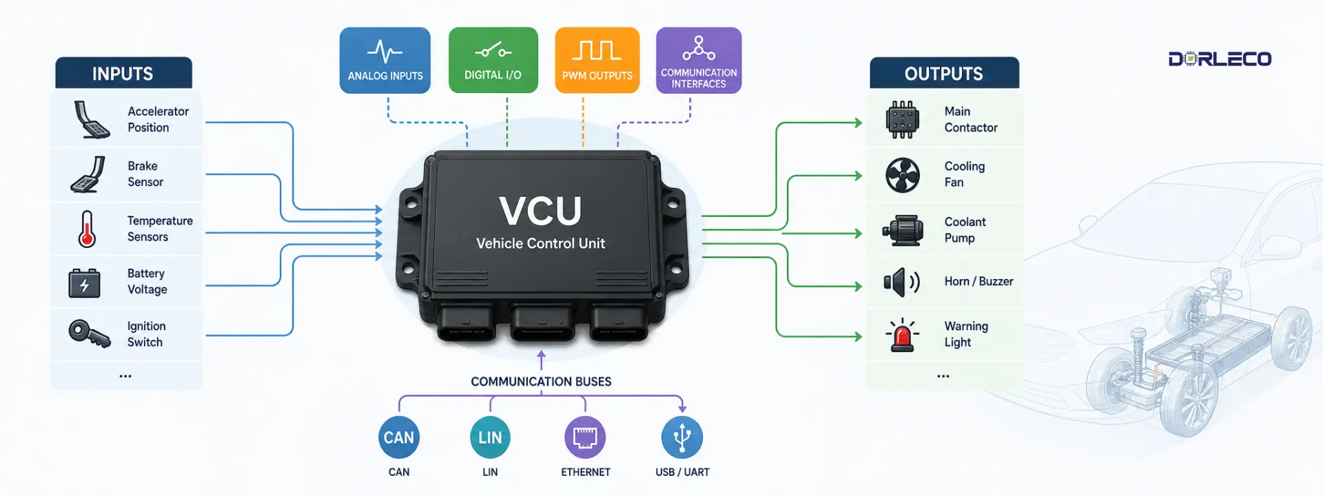
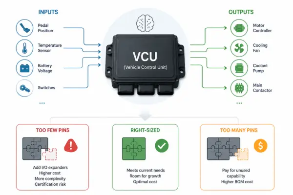 A VCU (Vehicle Control Unit) is the brain of an electric vehicle. It reads data from sensors, makes decisions, and sends commands to components like the motor controller, battery management system, and thermal systems. Every signal going in or out passes through an I/O pin — a physical connection on the controller. The total number and type of those pins are your I/O count. Getting this count wrong is a lot more painful than it sounds. Too few pins and you’re scrambling to add I/O expanders mid-program—a messy fix that adds cost, latency, and certification headaches. Too many and you’ve paid for capability you’ll never use, which eats into your BOM budget for every unit you ship. The problem is that most engineering teams underestimate I/O needs in the early phases of a program. The subsystem list grows. A new sensor gets added. The thermal management strategy changes. By the time you’re doing detailed design, that “comfortable” 48-pin VCU is looking a lot tighter than it did on the whiteboard.
 What types of I/O does a VCU need?
Not all I/O pins are created equal. A VCU needs several distinct types, and the balance between them depends heavily on your vehicle architecture. Here’s a breakdown of what you’ll encounter.1. Analog inputs (ADC)
Read variable voltage signals from sensors—throttle position, temperature sensors, current shunts, and pressure sensors. Typically 0–5 V or 4–20 mA ranges.
These are your biggest source of “I forgot about that” pins. Every sensor that produces a variable signal needs a dedicated ADC channel. Common analog inputs on EV VCUs include:- Accelerator pedal position sensor (APPS) — usually two channels for redundancy
- Brake pressure or position sensor — again, often redundant
- Motor temperature (NTC or PT100)
- Battery pack temperature sensors (if not all handled by BMS over CAN)
- Coolant temperature
- DC bus voltage monitoring
- 12V supply monitoring
- Any analog position sensors on gearboxes or actuators
2. Digital I/O (GPIO)
On/off signals. Inputs read switches, limit sensors, and Hall-effect triggers. Outputs drive relays, contactors, warning lights, and solenoids.
Digital I/O is where VCUs vary most between vehicle types. A simple two-wheeler might need a dozen digital I/O pins. A commercial truck can need 40 or more. Count up:- Inputs: ignition/key-on, mode switches, regenerative braking lever, seatbelt sensor, door interlocks, charge port lid, high-voltage interlock loop (HVIL), reverse switch
- Outputs: main contactor drive, pre-charge contactor, DC-DC converter enable, charge relay, horn, reverse buzzer, fault indicators, CAN wake-up
3. PWM outputs
Pulse-width modulation for continuously variable control—cooling fans, pumps, motor drive enable signals, and LED dimming. Frequency and resolution matter here.
PWM outputs are often underestimated because teams assume digital on/off control will be enough. In practice, variable-speed thermal management is almost always needed — especially in higher-power or fast-charging applications. Budget PWM channels for:- Coolant pump speed control
- Radiator fan(s)
- Cabin HVAC blower (if not via a dedicated ECU)
- Motor drive enable with soft-start requirements
- Instrument cluster or display backlighting
4. Communication interfaces
CAN, LIN, RS-485, Ethernet, or I2C/SPI for smart subsystems. Each bus uses dedicated pins — not general GPIO — and must be counted separately.
Every smart subsystem you add moves signal load off discrete I/O and onto a serial bus — but that bus still needs pins. A typical EV VCU needs:- CAN bus: 1–4 channels depending on network segmentation (powertrain, body, diagnostics)
- LIN bus: for low-cost body control modules, door handles, and lighting clusters
- Ethernet: increasingly required for OTA updates, ADAS nodes, and high-bandwidth diagnostics
- USB / UART: for programming, calibration, and data logging
How does vehicle type affect the I/O count?
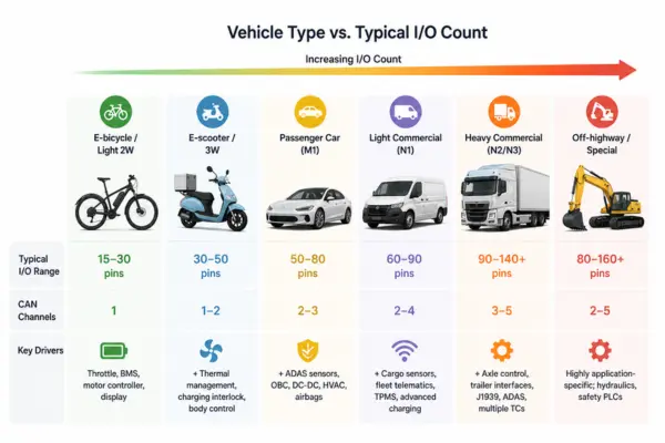 Vehicle type is probably the single biggest driver of VCU I/O count for EV requirements. A lightweight two-wheeler has dramatically fewer subsystems than a heavy commercial vehicle—and that difference can span a 3× to 5× range in total I/O count. Here’s a reference table based on typical production programs across different EV segments:
 | Vehicle type | Typical I/O range | CAN channels | Key drivers |
|---|---|---|---|
| E-bicycle / light 2W Pedal-assist, throttle-only | 15–30 pins | 1 | Throttle, BMS, motor controller, display |
| E-scooter / 3W Urban delivery, L-category | 30–50 pins | 1–2 | + Thermal management, charging interlock, body control |
| Passenger car (M1) BEV, up to 150 kW | 50–80 pins | 2–3 | + ADAS sensors, OBC, DC-DC, HVAC, airbags |
| Light commercial (N1) Delivery vans, ≤3.5 T | 60–90 pins | 2–4 | + Cargo sensors, fleet telematics, TPMS, advanced charging |
| Heavy commercial (N2/N3) Trucks, buses, 7.5–40 T | 90–140+ pins | 3–5 | + Axle control, trailer interfaces, J1939, ADAS, multiple TCs |
| Off-highway / special Construction, mining, AGVs | 80–160+ pins | 2–5 | Highly application-specific; hydraulics, safety PLCs |
Step-by-step: how to calculate your VCU I/O count for EV needs
1. List every subsystem the VCU talks to
2. Classify each connection: discrete or serial?
3. Build a signal-level I/O list
4. Tally up by signal type
5. Add your headroom buffer (20–30%)
6. Match against VCU platforms
What happens when you over- or underspec?
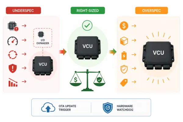
Underspecifying I/O
- Forces external I/O expander ICs mid-design
- Adds latency and complexity to signal chains
- Can require a full VCU platform change late in the program
- Creates re-certification risk under functional safety standards
- Delays SOP and increases NRE costs significantly
Overspecifying I/O
- Higher unit cost per VCU for unused capability
- Larger physical footprint — packaging constraints tighten
- Higher power consumption from a larger MCU
- May complicate ISO 26262 ASIL decomposition
- Excess capability may not be justified for lower-tier variants
How much I/O headroom should you add?
Most experienced VCU engineers recommend adding 20–30% headroom above your initial I/O count estimate. Apply this buffer per I/O type, not just to the grand total. For safety-relevant analog inputs like accelerator and brake signals, some teams apply an even higher buffer of 30–40% because late-stage redundancy requirements are hard to predict.
A few things that consistently consume “spare” I/O late in a program:- Additional diagnostic signals added by system safety analysis (FMEA, DFMEA)
- Regulatory requirements discovered after system design freeze—e.g., a new market requiring a different charge interlock topology
- Customer-requested features added post-design-intent sign-off
- Software-controlled power sequencing that turns out to need discrete lines rather than CAN commands due to timing requirements
- Additionally, include OTA update trigger signals or hardware watchdog lines to ensure functional safety.
Can a CAN bus reduce your physical I/O needs?
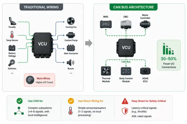 Yes — and this is one of the most impactful architectural decisions you can make early in a program. Replacing dedicated analog and digital lines with smart nodes communicating over CAN (or LIN for lower-bandwidth applications) can reduce discrete I/O requirements by 30–50% on a mid-size EV platform. The tradeoff is real, though. Every smart node you add needs its own MCU, firmware, power supply, and connector — which costs money and adds software complexity. For simple sensors that only report a single value slowly (like a pack temperature thermistor), running it directly to a VCU analog input is often simpler and cheaper than adding a CAN node to handle it. The general heuristic most teams use: if a subsystem has more than 4–6 distinct signals and needs its own local intelligence anyway (like a BMS, OBC, or ADAS ECU), put it on CAN. If it’s a simple sensor or actuator with 1–2 signals and no local processing needs, wire it directly to the VCU. Be careful about latency-critical signals. Throttle position, for example, is almost universally wired directly to VCU analog inputs rather than going over CAN — the 1–5 ms latency variability of a CAN bus is unacceptable for torque control loops. Safety standards like ISO 26262 may also require direct wiring for ASIL-rated signals to achieve the required diagnostic coverage.